The Telly Terminator

I received an interesting gift recently. It is a universal IR remote control which can be used to turn a large number of televisions/VCRs etc. on or off and it calls itself the Telly Terminator (strongly suggesting that the "off", rather than the "on", function seems to be the intended use of this little device).

Front and back side of the Telly Terminator (click for larger image)

The Telly Terminator is certainly not the only such product on the market. As far as I can tell the original is the TV-B-Gone which is even available in a hacker-friendly kit from Adafruit and has the honour of having its own tag on hackaday (furthermore, as far as I can see, the Telly Terminator has simply ripped its data from TV-B-Gone and I can't help wondering if the European Database Directive might have something to say about this).

Like Mitch Altman, the inventor of the TV-B-Gone, I find it too easy to waste time with a television and so I don't own one. For this reason I think the Telly Terminator was an apt gift and it works well. Also, having recently taken up a bit of a hobby in electronics, the Telly Terminator provided me with an excellent opportunity to "teardown" a very simple electronic toy. I wanted to know what it was doing and find out if its creators had simply ripped the TV-B-Gone data.

The USBee SX logic analyser

Several months ago I bought CWAV's USBee SX logic analyser. I had had some trouble getting Telit's GM862 GSM module and Maxstream/Digi's XBee module to communicate (when I was working on this project) and I bought the logic analyser to help solve the problem. As it turned out I solved the problem without the logic analyser and so my USBee ended up being a bit of a solution waiting for a problem. So this was another reason why I was eagre to have a poke around inside the Telly Terminator.

The USBee SX

Incidentally, although I like both the USBee SX and its accompanying USBee Suite, I can't resist mentioning the alternative Saleae logic analyzer. I found it hard to decide which of these two logic analyzers to buy and I was tempted to buy the Saleae analyzer simply because the inventor writes an interesting blog discussing his experiences creating and selling it. In the end I opted for the USBee SX because I was more confident of software support going forward and because it can also act as a signal generator which, as far as I could tell, the Saleae Logic cannot.

Inside the Telly Terminator

Inside the Telly Terminator there is a single simple circuit board:

Inside the Telly Terminator (click for larger image)

The board runs off a CR2032 3V cell battery (smoothed by a large 47uF electrolyic capacitor). There are 3 LEDs: an IR LED which is used to transmit the on/off signals, a small red LED which flashes while the IR LED is transmitting (as a signal to the user) and a white (phosphor based, I think) LED which enables the user of the Telly Terminator to pass it off as a simple torch in the event that he/she is foolish enough to turn off the wrong television. The brains of the operation is a Helios H5A02HP chip (in a 16 pin DIP package). A bit of poking around with a multimeter reveals the circuit details:

Telly Terminator schematic (click for larger image)

We see that pin 10 controls the IR LED (and so is the pin we are most interested in). Pin 16 controls the small red LED and pin 1 is connected to the switch K1. The part of the circuit connected to pin 15 puzzled me a little. The transistor Q2 will be on at power-on when the capacitor C5 is empty, and so pin 15 will be grounded, however once C5 is charged enough, Q2 switches off and never switches on again (indeed C5 will continue to charge through R6 even after Q2 switches off and so the voltage at the base of Q2 will drop well below the base emitter junction voltage). After Q2 switches off, C4 will charge till it reaches the voltage at pin 15. This much is obvious, but the question I asked myself was, why? I showed this to a friend who has more experience with these things and he suggested the plausible explanation that pin 15 is the reset pin, it is active low, it is internally pulled up and that it is desirable to have reset triggered for a brief while at power-on till things have stabalised. So my best guess is that pin 15 is the reset pin. In any case, it doesn't matter really and the rest of the circuit is straightforward.

Unfortunately Helios do not currently make the datasheet for their H5A02HP chip generally avaliable and did not respond to an email I sent them asking for it. For this reason I was unable to probe the chip in as much detail as I would have liked. All that I could get my hands on was the following block diagram:

H5A02HP block diagram

Incidentally, Helios create the H5A02HP chip as a simple speech synthesis chip so it's interesting to see it is the choice used for the Telly Terminator (presumably it was chosen because it was cost effective). It would be interesting to see exactly what the chip thinks it's doing when sending the on/off signals.

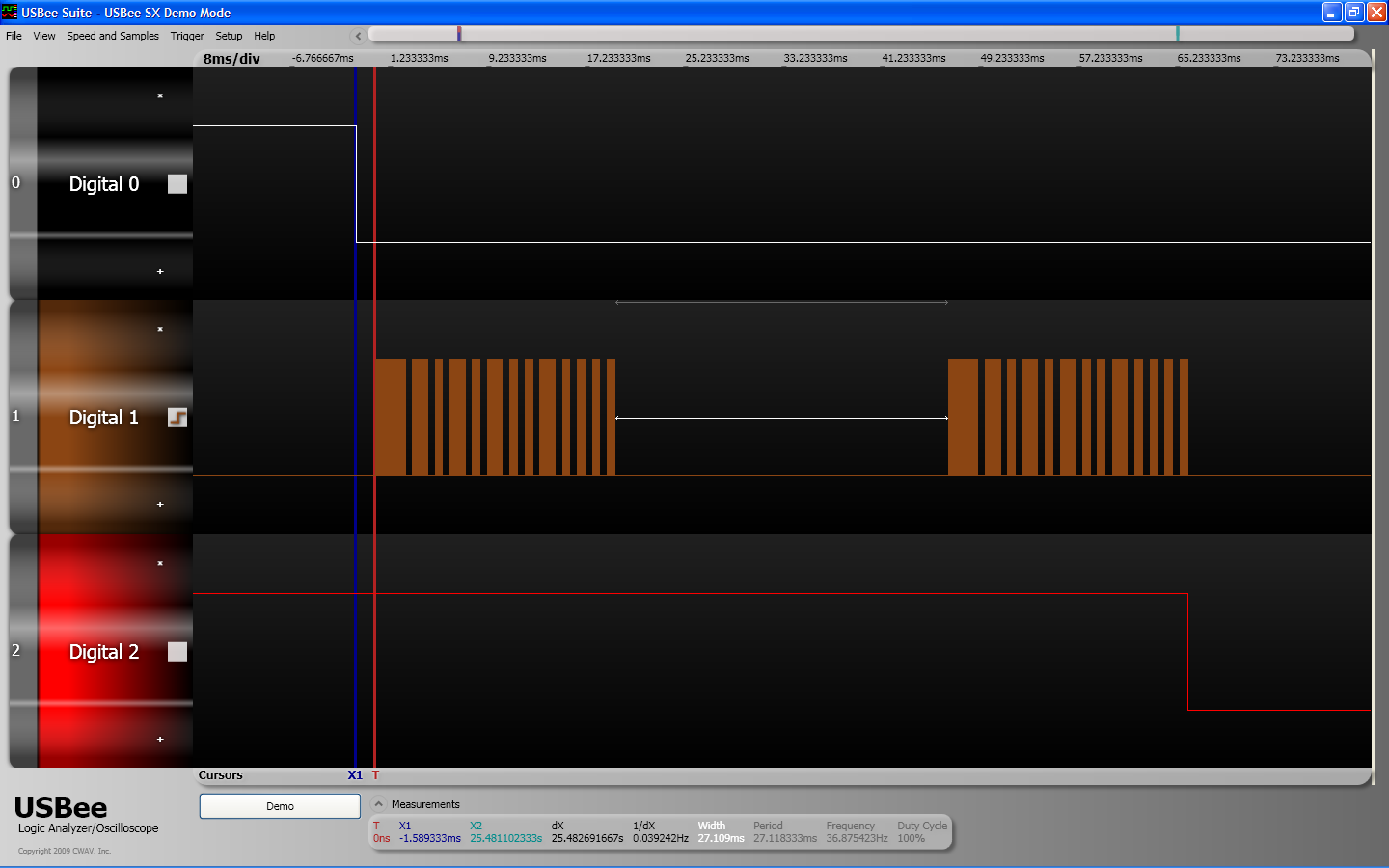
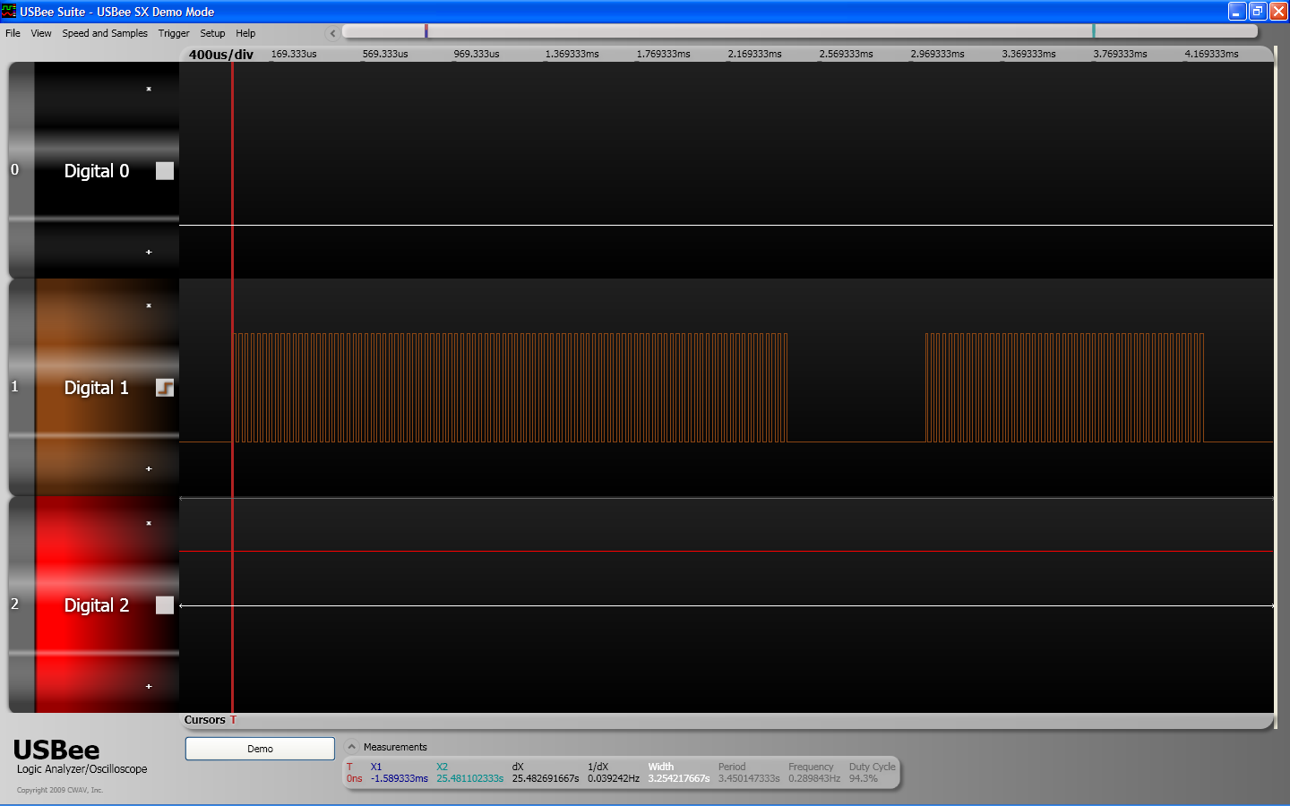
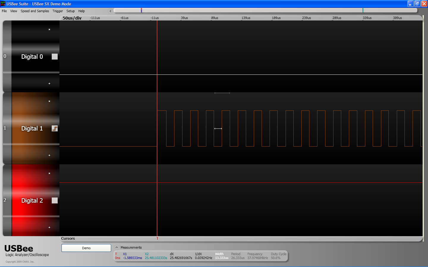
I used my USBee SX to probe the chip in standard fashion by connecting its various digital lines to the pins of the H5A02HP chip, triggering off several different events (including the state of the IR LED). According to my USBee SX, only pins 1, 10 and 16 change their state. Pin 10 sends out the on/off signals and carries the data I am most interested in. Pin 1 is grounded when the push switch is pressed and pin 16 sends a signal at ~2Hz which is responsible for causing the small red LED to flash (oddly though this signal is not completely regular). I would really like to investigate using an oscilloscope but unfortunately I do not own one (yet).

Screenshot from USBee Suite showing data on pins 1, 10, 16, shown as digital 0, 1, 2 respectively (click for larger image)

If you count the orange groups of spikes in above screenshot from USBee Suite (digital 1, i.e. pin 10), you will find that there are 46. These are the 46 on/off signals that the Telly Terminator sends out when it is triggered. They are all equally spaced approximately 390ms apart. To get a better look at the data, we need to zoom in. Zooming in on just the first spike in the above diagram we can see this on/off signal in more detail (evidently, it is sent twice).

On/off signal 1 (click for larger image)

Zooming in further on the first two pulses in the above diagram we can see that they are themselves a series of high/low states, i.e. we can see the carrier signal.

Signal 1 carrier (click for larger image)

Finally we zoom in on the carrier signal and see that it is a simple repeated square wave at ~38kHz with a 50% duty cycle.

Signal 1 carrier close-up (click for larger image)

Having sniffed the IR data (i.e. the data sent out pin 10), the next step is to try and decode it, at least partially. Before we do this, I thought it might be useful to carry this out for an on/off signal from an IR remote control whose protocol specification is available.

An RC6 remote control

My laptop is a HP Pavilion dv8000 and it came with a remote control which uses an extension of the Philips RC6 protocol. In this case, the chip which is running the show is Renesas Technology's M34283G2 chip (clocked using a 4Mhz (4.00L) ceramic oscillator). As far as I can tell, the protocol that the remote control uses is RC6 mode 6 with a 32 data bits which seems to be referred to both as RC6-6-32 and as MCE (a variation pioneered by Microsoft, I think).

RC6-6-32 on/off data (click for larger image)

The RC6 protocol has a carrier frequency of 36kHz and uses bursts of 16 periods to transmit data. The basic timing unit is thus 16/(36kHz) = 444.44(4)us and bits are encoded using Manchester encoding. The signal contains the following fields which I have marked in corresponding colours in the above screen shot from USBee Suite: The leader pulse and the start bit should always be as above. We read the data in the mode bits by remembering the Manchester encoding and find that the data is 110 in binary, i.e. 6 in decimal. This is expressed by saying that we have an instance of RC6 in mode 6. The trailer bit is a twice as long as a normal bit and contains the value 0. Finally this leaves the data bits, of which there are 32. In the above case these contain the data: 1000 0000 0001 0001 0000 0100 0000 1100 in binary or 0x8011040C in hex. Presumably these 32 bits of information can be broken down further into address/control/information fields etc. but I'm happy to leave things at this point. I can at least confirm that my laptop understands what 0x8011040C means since I accidentally switched it off using the remote the first time I was trying to sniff this signal using my USBee.

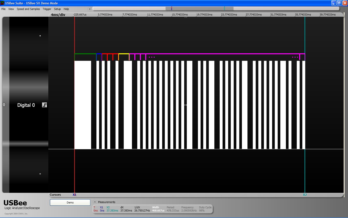
It is pretty easy to decode the above data for my laptop remote by hand just because there is so little of it. However I also wanted to decode the signals sent by the Telly Terminator a little so I wrote a quick python script to help analyse the data a little. The script reads the sampled data generated by the USBee, separates out the 46 different on/off signals and in each case calculates the carrier frequency, the total signal length, the carrier duty cycle and the timing data for the pulses of carrier signal in each case. For example, the script generates the following using the data from my laptop remote control.

  Signal 0 : 36.17kHz, 36.921ms, 35%
  On time (periods)	Off time (periods)
  2.654ms (96.0)		0.885ms (32.0)
  0.442ms (16.0)		0.443ms (16.0)
  0.442ms (16.0)		0.443ms (16.0)
  0.442ms (16.0)		0.889ms (32.1)
  0.443ms (16.0)		0.881ms (31.9)
  1.327ms (48.0)		0.889ms (32.1)
  0.443ms (16.0)		0.450ms (16.3)
  0.443ms (16.0)		0.450ms (16.3)
  0.442ms (16.0)		0.451ms (16.3)
  0.442ms (16.0)		0.451ms (16.3)
  0.442ms (16.0)		0.451ms (16.3)
  0.442ms (16.0)		0.451ms (16.3)
  0.442ms (16.0)		0.450ms (16.3)
  0.443ms (16.0)		0.450ms (16.3)
  0.443ms (16.0)		0.450ms (16.3)
  0.885ms (32.0)		0.893ms (32.3)
  0.443ms (16.0)		0.450ms (16.3)
  0.443ms (16.0)		0.450ms (16.3)
  0.885ms (32.0)		0.893ms (32.3)
  0.442ms (16.0)		0.451ms (16.3)
  0.442ms (16.0)		0.451ms (16.3)
  0.442ms (16.0)		0.451ms (16.3)
  0.442ms (16.0)		0.451ms (16.3)
  0.885ms (32.0)		0.892ms (32.3)
  0.443ms (16.0)		0.450ms (16.3)
  0.443ms (16.0)		0.450ms (16.3)
  0.443ms (16.0)		0.450ms (16.3)
  0.443ms (16.0)		0.450ms (16.3)
  0.443ms (16.0)		0.450ms (16.3)
  0.885ms (32.0)		0.446ms (16.1)
  0.443ms (16.0)		0.889ms (32.1)
  0.442ms (16.0)		0.451ms (16.3)
  0.443ms (16.0)
  
The script has thus estimated the carrier frequency as 36.17kHz, the total signal length as 36.921ms and the duty cycle of the carrier as 35%. The script has also calculated that the first burst of carrier marking lasts for 2.654ms which is 96.0 periods of carrier frequency, this is followed by 0.885ms of space which is 32.0 periods of carrier frequency and so on.

Python sourcecode

Although it's not exactly a work of art (to say the least) I thought I might as well make the source code to the decoding script available.


  import sys, csv

  SPACE = 0
  MARK = 1

  class StreamWithPush:
     def __init__(self, data):
        self.data = data
        self.buffer = []
     def __iter__(self):
        return self
     def next(self):
        if len(self.buffer) == 0:
           return self.data.next()
        else:
           x = self.buffer[-1]
           del self.buffer[-1]
           return x
     def push(self, x):
        self.buffer.append(x)
     def push_l(self, l):
        self.buffer.extend(l)

  class Signal:
     def __init__(self, frequency, duty_cycle, data):
        self.frequency = frequency
        self.duty_cycle = duty_cycle
        self.data = data
     def __str__(self):
        s = 'On time (periods)\tOff time (periods)\n'
        tm = 0
        assert len(self.data) % 2 == 1, 'Uh oh.'
        for i in range(len(self.data) / 2):
           s += '%.3fms (%.1f)\t\t%.3fms (%.1f)\n' % (self.data[2*i][1] * 1000, self.data[2*i][1] * self.frequency,
                                                     self.data[2*i+1][1] * 1000, self.data[2*i+1][1] * self.frequency)
           tm += self.data[2*i][1] + self.data[2*i+1][1]
        s += '%.3fms (%.1f)' % (self.data[-1][1] * 1000, self.data[-1][1] * self.frequency)
        return ('%.2fkHz, %.3fms, %d%%\n' % (self.frequency * 0.001, tm * 1000, int(self.duty_cycle * 100))) + s

  def get_freq_dcycle(mark_data, sample_tm_ns):
     # TODO Check mark_data is consistent, i.e. all same frequency and duty cycle (or even same shape).
     tot = on = 0
     for (h, l) in mark_data:
        tot += h + l
        on += h
     return (len(mark_data) / (tot * sample_tm_ns * 1e-9), float(on) / tot)

  def get_signals(pattern, sample_tm_ns):
    NEW_SIG_TM = 0.38 # I measure a gap of ~391ms between signals. TODO learn this from the data.
    signals = []
    i_pattern = iter(pattern)
    done = False
    while not done:
       signal_data = []
       mark_data = []
       l_mark = 0
       while True:
          try:
             packet = i_pattern.next()
          except StopIteration:
             signal_data.append((MARK, l_mark * sample_tm_ns * 1e-9))
  	   done = True
  	   break
          if packet[0] == SPACE:
             signal_data.append((MARK, l_mark * sample_tm_ns * 1e-9))
  	   l_mark = 0
             if packet[1] * sample_tm_ns * 1e-9 >= NEW_SIG_TM: # End of this signal.
                break
             else:
                signal_data.append((SPACE, packet[1] * sample_tm_ns * 1e-9))
          else: # packet[0] == MARK
             l_mark += packet[1] + packet[2]
             mark_data.append((packet[1], packet[2]))
       (frequency, duty_cycle) = get_freq_dcycle(mark_data, sample_tm_ns)
       signals.append(Signal(frequency, duty_cycle, signal_data))
    return signals

  def markate(csv_data, channel):
     pattern = []
     marking = False
     l_not_marking = l_last_period = 0
     slippage = 15 # samples.
     sample_tm_ns = 333.333333333 # nanoseconds between samples. TODO learn this from data and verify all samples consistent.
     for row in csv_data:
        (tm, v) = (int(''.join(row[0].split('.'))), row[channel])
        if not marking:
           if v == '0':
              l_not_marking += 1
           else:
              marking = True
              pattern.append((SPACE, l_not_marking))
              l_not_marking = l_last_period = 0
              csv_data.push(row)
        else: # marking == True
           if v == '1':
              for (n_ones, row) in enumerate(csv_data):
                 if row[channel] != '1':
                    break
              n_ones += 1
              buffer = []
              for (n_zeros, row) in enumerate(csv_data):
                 if row[channel] != '0':
                    csv_data.push(row)
                    break
                 if l_last_period > 0:
                    d = n_ones + n_zeros + 2 - l_last_period
                    if d > 0:
                       buffer.append(row)
                    if d > slippage:
                       csv_data.push_l(buffer)
                       n_zeros -= slippage
                       marking = False
                       break
              n_zeros += 1
              pattern.append((MARK, n_ones, n_zeros))
              l_last_period = n_ones + n_zeros
           else: # v == '0'
              sys.stderr.write('Uh oh\n') # Shouldn't happen and causes us to lose data.
              marking = False
              csv_data.push(row)
     return (sample_tm_ns, pattern[1:]) # Exclude first element which is just ('SPACE', 0).

  def main(argv=None):
     if argv is None:
        argv = sys.argv
     if len(argv) != 3:
        sys.stderr.write('Usage: %s  \n' % argv[0])
        sys.exit(1)

     csv_data = StreamWithPush(csv.reader(open(argv[1])))
     csv_data.next() # Field headings.
     (sample_tm_ns, pattern) = markate(csv_data, int(argv[2]) + 1)
     signals = get_signals(pattern, sample_tm_ns)
     for (i, sig) in enumerate(signals):
        print 'Signal %d : %s\n\n' % (i, sig)

  if __name__ == '__main__':
     sys.exit(main())
  

The Telly Terminator data

Using the above script, I decoded the data for the 46 separate on/off signals which the Telly Terminator sends. The results are here. Unsurprisingly, the Telly Terminator data looks like a rip of the North American TV-B-Gone data (rather than the European TV-B-Gone data). I spot checked the first five signals sent by the Telly Terminator and found that they match those sent by the North American TV-B-Gone in the same order and with the same repetitions. Not quite all signals match (indeed the TV-B-Gone sends 56 signals, 10 more than the Telly Terminator) but this is presumably the result of the Telly Terminator data having been ripped from an earlier version of the TV-B-Gone data.

Finally I thought I'd also mention that USBee Suite can be downloaded for free and so I might as well make the session file with my Telly Terminator data and my laptop's remote control data available for download.