
I was less than absolutely delighted at this development as it was 2am on a Tuesday evening/Wednesday morning and I had to be up for work at ~7am. However getting annoyed wasn't going to help so I decided to try waiting for someone else to enter/exit the building. In those silent minutes it occurred to me how useful it would be if I had a remote control for my apartment's intercom. The intercom can open the building door at the press of a switch. There was nothing I could do at the time but I liked the idea and decided that I'd look into it the next day. I thought it might be worth writing a little about where these thoughts eventually lead me.


From the user's point of view, the intercom has three components:
I was very keen that whatever hardware I ended up adding to my intercom would not alter the look of the hall in my apartment. I thus decided that anything I was going to use would have to fit inside the intercom enclosure. Also, after a few tests I discovered that only a few milliwatts of power were available in the circuits powering the intercom so whatever I was going to add there would almost certainly have to be battery powered. I wasn't so keen on using batteries until I had the idea that since the speaker for the intercom has to be rung anyway for the switch to work, if I could have a device which was off (and so drawing no current from the batteries) except for a short period after the speaker was rung then I could expect acceptable battery life. Furthermore I had the idea that I could put a small low power short range RF tranceiver in the intercom which would receive commands from a GSM module elsewhere in my apartment. This way the GSM module could be plugged in and always on and very little power would be needed in the intercom, plus it's easy to get very small RF transceivers that would easily fit inside the intercom enclosure. I decided on this as a solution and bought the following items (amongst others) from Sparkfun:
The GM862 GPS module is superb. My favourite feature of it is that it has a python interpreter on it! You can write simple python programs on your PC, upload them to the module and then have them control the module. This obviates the need for another microcontroller telling the GM862 module what to do. It is easy to send and receive text messages and phone calls. The built in GPS module (though of no use to me in this project) is also very easy to use and although I have not yet done it, I believe it is easy to open GPRS connections using the module. The module also has a host of useful GPIO pins which are very useful and a serial port (it has many other features too!).
The XBee modules are also great (though Maxstream's decision to remove IO line passing in the XBee series 2 modules is disappointing). They have two modes: transparent where they pair up and behave like a wire-less serial connection and API mode where the user communicates with the modules via their serial ports and can send simple packets back and forth between the modules to determine and set their state, including reading and writing values on their IO pins.
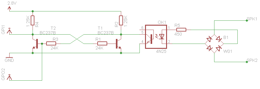
I used the XBees in API mode for this version of the project. I connected an opto-isolator up to one of the digital IO pins on the XBee module in the intercom so that I could trigger the switch for the intercom using the XBee. (In fact I discovered that I needed to use a Darlington coupled opto-isolator for enough current to trigger the intercom switch.)
I discovered that an XBee series 2 module (running the ZB 2.5 end device firmware) can be put in pin sleep mode where it consumes < 1uA of current and furthermore that if pin 20 (the commissioning button pin) is grounded once, the module will wake up for 30 seconds and broadcast a Node Identification Indicator packet (API identifier value: 0x95) to the network letting other nodes know it is awake. This feature was perfect and saved me having to manually create my own micro-power timed wake-up circuits for the XBee in the intercom. However I discovered that sometimes this packet did not arrive and so I jumpered pin 20 to pin 19 which I set as a digital input. I then configured the intercom XBee to transmit a packet when the state of DIO19 changed. I found that these Data Sample Rx Indicator packets (API identifier value: 0x92) were always transmitted and so a packet was always sent out to the network when the intercom XBee was woken up using pin 20.
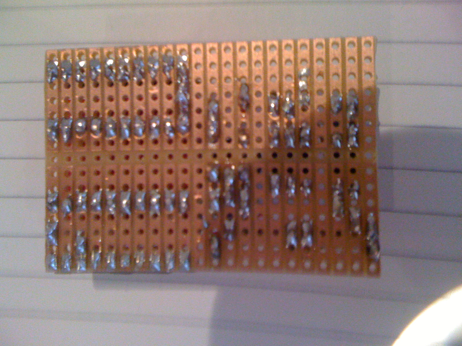
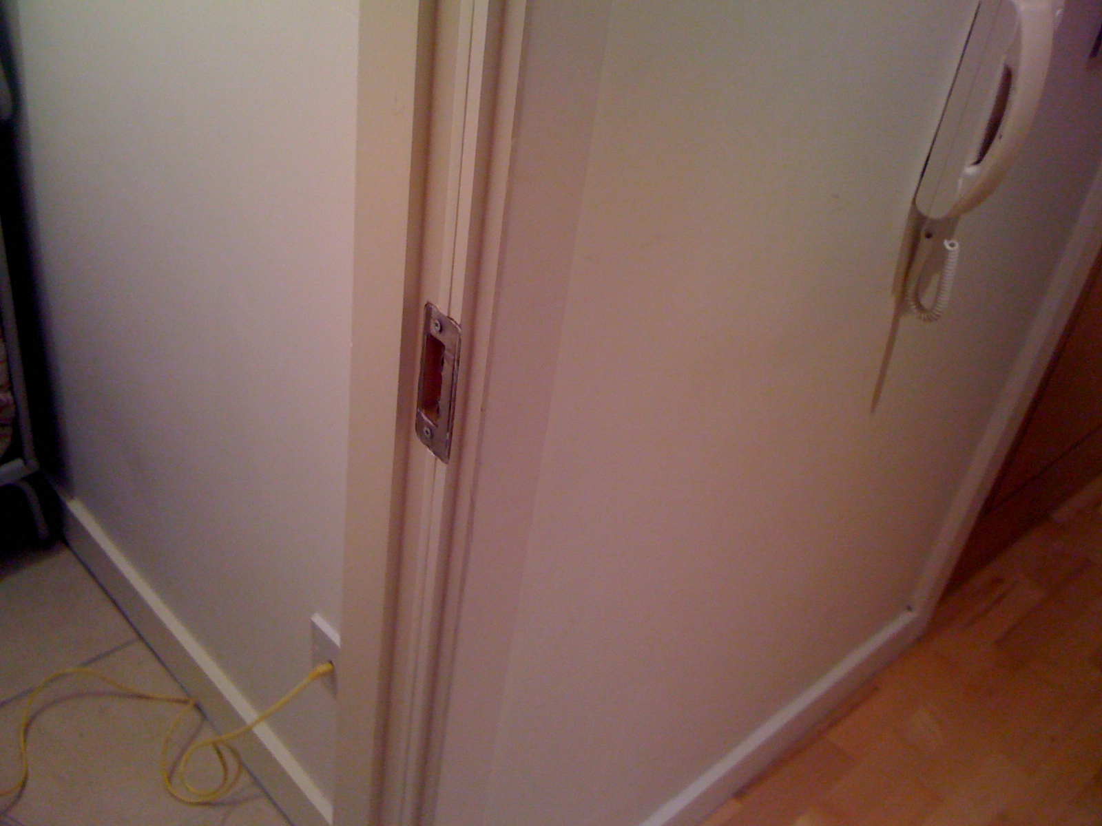
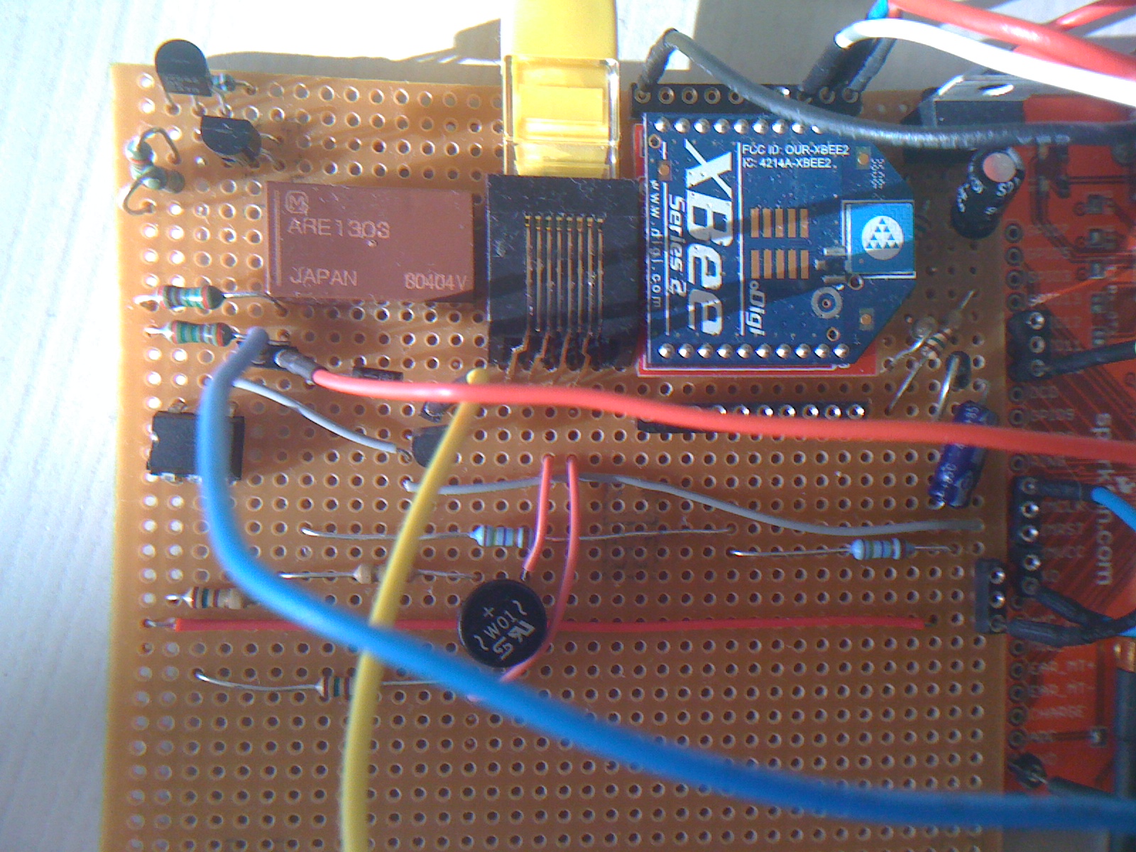
All I had to do as regards the intercom was then to arrange for pin 20 to be grounded when the speaker was rung. This was easily accomplished used a bridge rectifier, a resistor and another opto-isolator. The schematic of the simple circuit I used appears in version 2 below. Here are some pictures of the XBee for the intercom mounted on some Veroboard together with the simple circuits to trigger the intercom switch and to wake up when the speaker is rung:

As a result of this, all I had to do was to have the GM862 module plugged in elsewhere in my apartment, connected (serially) to another XBee waiting to hear the packets indicating that the speaker had been rung. If the speaker was rung, the module checked if it had received a text message recently from the correct person, containing the correct password. If so, the GM862 module used its XBee to send an API packet to the XBee in the intercom to cause it to trigger the Darlington opto-isolator and trigger the intercom switch. A Remote AT Command Request packet (API identifier value: 0x17) was used to do this. A simple python script was running on the GM862 module controlling all of this.
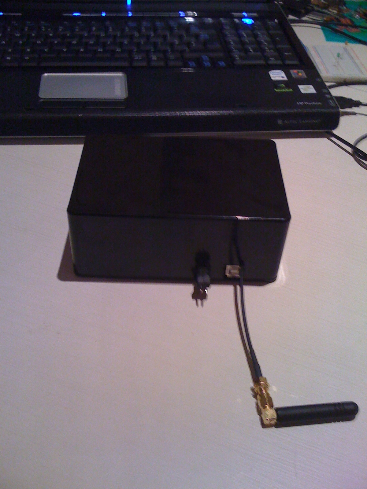
Here's a (pretty blurry!) picture of the GSM module inside it's enclosure. You can see the GSM aerial, the power connector and the USB port on Sparkfun's GM862 USB evaluation board.
So that's a brief sketch of version 1. I've omitted many details and smoothed over quite a few bumps but that was the general set up.
I decided this was worth the effort and set about carrying it out. The idea was to plug the GSM module into a plug socket in the hot press and connect it to the intercom using the cable I would run from the hot press to the intercom. No wireless modules and no batteries would be necessary. So I set about running the cable.
I'd never really done any DIY but I was careful to think things through and was very satisfied with the results I got. I decided to use 8 core CAT5e cable and mount an RJ45 socket in the hot press which the CAT5e cable would connect to various junctions in the intercom circuit board. In fact I just need 4 of the 8 wires in the CAT5e cable (2 for the switch, 2 for the speaker) but I thought it would be worth having extra wires for any potential future features.
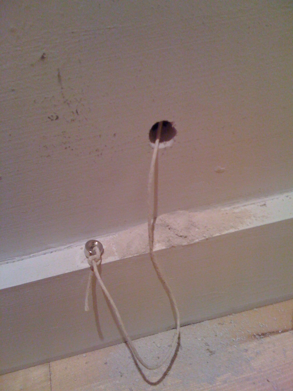
I don't know how people normally do cabling jobs like this but I decided to use magnets to run the cable behind the wall. I bought a **VERY** powerful F4335 neodymium rare earth magnet from Magnet Expert (which they allege can exert a force of 120N in ideal circumstances!). The internal walls in my apartment are made of 1.25cm plasterboard (drywall if you're from the US). I also placed a small magnet tied to some string into the wall using the hole that the existing cable for the intercom enters by. I then guided this small magnet and string behind the wall using my super magnet. It worked like a dream! There were various complications involving support beams, turning a corner and a door frame but I studied the geometry carefully and also had bought a cheap but sufficient snake scope so in the end I managed to succeed.
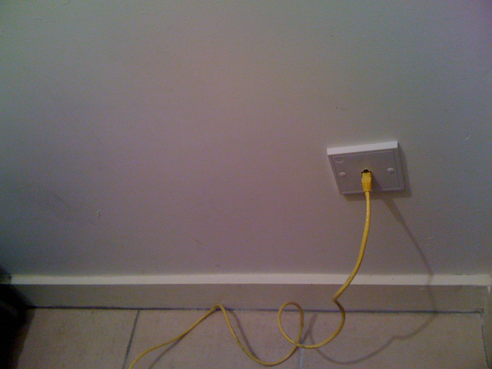
Once I had succeeded in running the cable from the intercom to the hot press, I mounted the RJ45 socket and used Polyfilla (multipurpose followed by fine surface) to cover my tracks where I had had to make a few holes in the hall wall. Here are a few pictures I took at various stages of this wiring job:


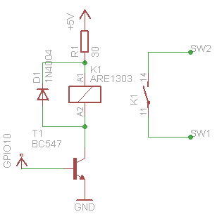
For this second function I needed the GSM module to hear the speaker. However there are no interrupts available on the GM862 pins so I would have to poll for the speaker. This would mean I could miss it if the module was busy doing something else and after noting that the module is particularly slow when it is waiting for the SIM to process a command, I realised that I would be lucky if I ever caught the speaker. I decided that the solution would be to have the speaker set an SR latch which the GSM module would poll and reset. I was keen to get this working quickly so I built a latch by hand using the transistors and resistors already available to me in my parts box. By the time I was building this I was less ignorant about electronics and so understood the importance of ensuring transistor saturation. I thus calculated my resistor values carefully and made sure that the current gain I was getting was safe even if the transistor beta \( h_{fe}\) was at least a factor of 10 worse than the data-sheet claimed it could be. See the schematic for the circuit I used, the circuit to tap the speaker current is also shown.

So that's it really! I found this a very enjoyable, educational and satisfying project. I include the python scripts running on the GSM module below (with passwords and phone numbers removed!). There are still lots of small changes and improvements I can think of but I'm happy to say this works well in its current form. Here's a picture of the complete Veroboard containing the circuits discussed above (on the right of the image we can also see the edge of Sparkfun's USB evaluation board for the GM862 module):
main.py
  import SER, MOD, sys

  class SerWriter:
     def write(self, s):
        t = '%d ' % MOD.secCounter()
        for c in s:
           if c == '\r' or c == '\n':
              t = t + ' '
           else:
              t = t + c
        SER.send(t + '\r\n')

  SER.set_speed('9600', '8N1')
  sys.stdout = sys.stderr = SerWriter()
  print 'Serial line set up'

  """
  I have two python files and the below import at the bottom of this script for two reasons:
  1. The below script will be compiled to a python object file and not recompiled each time
     we tun this script. This saves time on startup because Telit's python compiler is VERY
     slow.
  2. It is almost impossible to debug compile errors without getting the output of stderr and
     the setup I have here allows me to see them.
  """
  import sentry
  import MDM, MOD, GPIO, SER, sys

  def get_till_empty(get):
     # Reads from stream determined by calling get till nothing left.
     # Might alter this to be able to handle case when get takes arguments.
     # (Then could use it for the SER and MDM receive functions too.)
     s = ''
     while 1:
        t = get()
        if t == '': # TODO: Robustify this termination condition.
           break
        s = s + t
        MOD.sleep(5) # Not sure if this helps but no harm.
     return s

  def parse_text_messages(s):
     l = []
     lines = s.split('\r')
     i = 0
     while 1: # StopIteration exception not supported in Python 1.5.2+ so have to do it old fashioned way.
        line = lines[i].strip()
        if line[:5] == '+CMGL':
           # TODO: Insert IndexError exception handling below.
           fields = line.split(',') # TODO: Handle quotes properly. Date/time mangled a bit by this. Also find out what fields[3] is (empty in all my examples).
           msg_id = int(fields[0][6:])
           sender = fields[2] # TODO: Fix up formatting issues like leading + and quotes.
           time_and_date = fields[4] + ' ' + fields[5] # TODO: Format this into more useful structure.
           i = i + 1
           body = lines[i].strip()
           l.append((msg_id, sender, body, time_and_date))
        i = i + 1
        if i >= len(lines): # OK to check this here since ''.split('\r') == [''], i.e. length 1 list.
           break
     return l

  def open_door():
     sys.stdout.write('Welcome home!')
     GPIO.setIOvalue(UNLOCK_PIN, 1)
     MOD.sleep(DELAY)
     GPIO.setIOvalue(UNLOCK_PIN, 0)
     global last_open_time
     last_open_time = MOD.secCounter()
     """
     Note that the open signal for the door also triggers the speaker so this speaker sound has to be
     finished by the time we get to the below, where we try to latch the speaker state low again.
     If it isn't, the latch will just revert to the speaker high state and we could end up sending
     the open signal on each iteration of the outer loop until open_on_speaker_timeout is up
     which would be pretty silly. The delays in place are enough though I think.
     """
     sys.stdout.write('Setting BELL low')
     set_speaker_low()

  def set_speaker_low():
     GPIO.setIOvalue(BELL_WRITE_PIN, 1)
     MOD.sleep(DELAY)
     GPIO.setIOvalue(BELL_WRITE_PIN, 0)

  def report_state(destination, message):
     MDM.send('AT+CMGS=%s,145\r' % destination, DELAY)
     MOD.sleep(DELAY)
     response = get_till_empty(MDM.read)[-4:]
     if response == '\r\n> ':
        sys.stdout.write('Texting %s to %s' % (message, destination))
        MDM.send(message + chr(0x1A), DELAY)
     else:
        sys.stderr.write('Unexpected response %s when texting %s to %s' % (response, message, destination))

  DELAY = 20 # 0.1s of second.
  SIM_PIN = xxxx
  BELL_READ_PIN = 1 # Important to use pin 1 here as need extra transistor buffer so don't draw to much current from latch circuit.
  BELL_WRITE_PIN = 2 # Important to use pin 2 here as need open collector output for my latch to work.
  UNLOCK_PIN = 10
  UNLOCKING_KEYS = { '"+35386xxxxxx"' : 'xxxxxx' } # I could store this dictionary in the SIM address book rather than the code.
  MAX_UNLOCK_TIME = 300 # 5 minutes.

  # Unlock SIM (and consequently register with network).
  MDM.send('AT+CPIN=%d\r' % SIM_PIN, 0)
  while MDM.receive(DELAY).find('READY') == -1: # TODO: Perform better match than just find('READY').
     MDM.send('AT+CPIN?\r', 0)
     MOD.sleep(DELAY)
  sys.stdout.write('Module ready')

  # Set our message format to text (not PDU).
  MDM.send('AT+CMGF=1\r', 0)
  MOD.sleep(DELAY) # Just in case module needs a moment to digest this command.
  MDM.send('AT+CMGD=1,4\r', DELAY) # Clear out all text messages before we start.
  MOD.sleep(DELAY * 2)

  GPIO.setIOdir(BELL_READ_PIN, 0, 0)
  GPIO.setIOdir(BELL_WRITE_PIN, 0, 1)
  GPIO.setIOdir(UNLOCK_PIN, 0, 1)

  last_open_on_speaker_text_time = 0
  open_on_speaker_timeout = 0
  last_open_time = 0
  last_speaker_time = 0
  sys.stdout.write('Entering main loop')
  while 1:
     sys.stdout.write('Looping')
     MDM.send('AT+CMGL="ALL"\r', DELAY) # DELAY is just a maximum wait here; in general we're quicker than this.
     for (msg_id, sender, body, time_and_date) in parse_text_messages(get_till_empty(MDM.read)):
        sys.stdout.write('Deleting message with id: %d' % msg_id)
        MDM.send('AT+CMGD=%d\r' % msg_id, DELAY)
        MOD.sleep(50)
        if sender in UNLOCKING_KEYS.keys() and body.startswith(UNLOCKING_KEYS[sender]):
           sys.stdout.write('Message %s, %s matched.' % (sender, body))
           body_fields = body.split()
           if len(body_fields) == 2:
              try:
                 open_on_speaker_timeout = min(MAX_UNLOCK_TIME, int(body_fields[1]))
                 last_open_on_speaker_text_time = MOD.secCounter()
              except ValueError:
                 sys.stderr.write('Unrecognised field "%s". Was expecting timeout in seconds.' % body_fields[1])
           else:
              open_door()
        elif sender in UNLOCKING_KEYS.keys() and body == 'state':
           report_state(sender,
                        'now=%d\n'\
                        'last_speaker=%d\n'\
                        'last_open=%d\n'\
                        'last_open_on_speaker_time=%d\n'\
                        'last_open_on_speaker_timeout=%d'\
                        % (MOD.secCounter(), last_speaker_time, last_open_time, last_open_on_speaker_text_time, open_on_speaker_timeout))
        else:
           sys.stdout.write('Ignoring unmatched message: %s, %s' % (sender, body))
     if GPIO.getIOvalue(BELL_READ_PIN) == 1:
        sys.stdout.write('BELL state high')
        last_speaker_time = MOD.secCounter()
        if MOD.secCounter() - last_open_on_speaker_text_time < open_on_speaker_timeout:
           open_door()
        set_speaker_low() # It will in fact already be low if we just called open_door() but that's fine.
     else:
        sys.stdout.write('BELL state low')
     MOD.sleep(DELAY)
     if get_till_empty(SER.read).find('quit') != -1:
        sys.stdout.write('OK quitting python')
        break