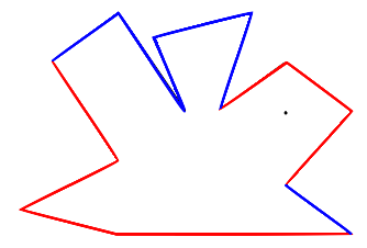
Input: A point in the plane, known as the eye, together with a list of points in the plane which form the vertices of a polygon. All coordinates are integers.For example, in the polygon below, the edges coloured red are those visible to the black dot representing the eye:
Output: The set of sides of the polygon which are at least partially visible to the eye (looking in any direction).
The algorithm is based around a function with the following type:
lineSegMeetsLineSeg :: LineSeg -> LineSeg -> Bool
clipEdge :: Edge -> LineSeg -> ViewPort -> ViewPortclipByOneSide :: ViewPort -> LineSeg -> Maybe ViewPortclipByAllSides :: Point -> [Point] -> Int -> Maybe LineSegAnd that's it! If we wanted to speed things up we could also use 2-dimensional back-face culling but there is no need.
Although it was a slightly tedious exercise translating the Haskell code to C++, it was interesting to see the sort of C++ code that resulted. It seemed to me to be a good example of how it is possible to write good quality code with almost no object orientation. If nothing else, this exercise convinced me to try harder for referential transparency when writing C++ in future.
In any case for those who might be interested, here is a link to both the C++ and Haskell sources. I think the algorithm is particularly easy to understand in the Haskell implementation.
One final comment on the Haskell. The key function has the following type:
clipByOneSide :: ViewPort -> LineSeg -> Maybe ViewPort
  c :: (Monad m) => (a -> b -> m a) -> m a -> b -> m a
  c f y z = y >>= ((flip f) z)

  scanM :: (Monad m) => (a -> b -> m a) -> a -> [b] -> [m a]
  scanM f x l = scanl (c f) (return x) l
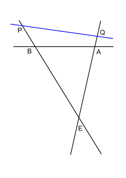
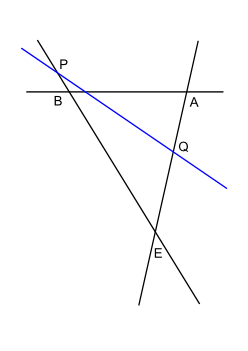
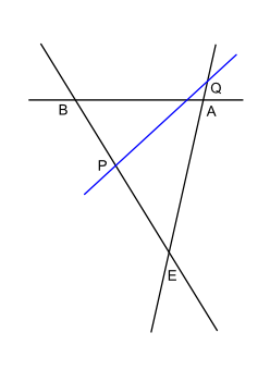
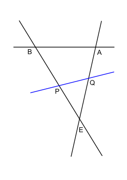
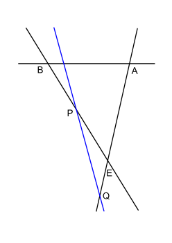
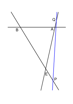
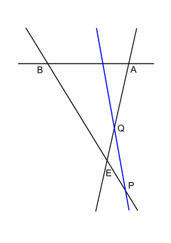
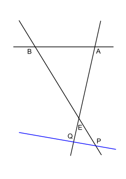
Suppose we imagine the viewport triangle and ask ourselves what are the different ways a line can intersect it. (This line represents the line containing a side which might be clipping the viewport.) For now let's exclude the case where the line passes through a vertex of the viewport and see how many cases there are. In the pictures below, E represents the eye and A and B are points on the side to which the viewport belongs. The "clipping" line is in blue:
Case 1
|
Case 2
|

Case 3
|
Case 4
|
Case 5
|
Case 6
|
Case 7
|
Case 8
|
Case 9
|
Evidently there are 9 cases because there are 3 different locations for P (behind E, between E and B, beyond B) and 3 for Q. In fact we can simplify things by introducing the line at infinity and so passing to the projective plane. If we do this then the cases "behind E" and "beyond B" are the same since the two ends of the line BE are connected at infinity. Similarly for Q. Thus there are now just 2x2 = 4 cases instead of 9 overall. In terms of the picture above, these four cases are:
First note that the viewport actually defines a triangulation of the entire projective plane. All we have to do is extend its three sides to full projective lines. Here is a picture of what happens:

All very well but what's the point? Well, now note that in fact we also get a natural induced triangulation of the dual projective plane with the same number of vertices, edges and faces as the original. This is because three points in general position (i.e., non-collinear) in the projective plane uniquely determine three points in general position in the dual projective plane (i.e., three non-concurrent lines). In other words, it is equivalent to specify a triangle by providing its vertices or its sides. To spell this out, recall that the points of the dual projective plane are lines of the original and that the lines of the dual projective plane are points of the original (and that the incidence relation between points and lines is unchanged). The 4 faces of the dual projective plane triangulation correspond to the 4 2-dimensional families of lines that have no degenerate intersections (i.e., do not pass through A, B or E). The 6 edges of the dual triangulation correspond to the first set of 1-dimensional families of degenerate intersections for lines which pass through exactly one of A, B, E and the 3 vertices of the dual triangulation are the 3 lines AB, BE, EA.
Thus the different types of behaviour of the clipping line, including all its degenerate intersection possibilities, correspond to where it sits, as a point in the dual projective plane, in terms of the triangulation of the dual projective plane that is naturally induced by the viewport triangle. I find it pleasing that something which can be annoying, namely the degenerate intersection cases, can be described so concisely.
One final word on the use of the projective plane. Since the problem of clipping concerns only incidence geometry, we are free to employ the full group of projective transformations as a tool to simplify our problem. I didn't bother, but it is easy to find a projective transformation that takes the eye to infinity and the vertices A, B to (0, 0), (1, 0) and the lines AE, BE to vertical lines. Doing this transforms the viewport into a semi-infinite rectangle which can greatly simplify and speed up clipping calculations. I believe this is the standard approach when clipping in three dimensions.
Lastly note that if we really wanted to opt for purity in our algorithm, we could construct an algorithm which is only told which of the 13 cases it is in and then told the ordering of the 4 points on the clipping line that are P, Q, I, J where P, Q are as above and I, J are the vertices of the side which define the clipping line. I considered implementing this but decided there were more cases than I wanted to handle especially as we need to consider cases when some of the points P, Q, I, J coincide. I believe this could be done elegantly though.
Having already indulged myself with ludicrously expansive comments on the projective plane I will keep it brief and say only that good algorithms would be based around spatial subdivision data structures (e.g., BSP trees with nodes corresponding to lines through polygon sides). The point is that if we subdivide the plane into regions in which the set of sides visible to the eye is constant then we need only decide which region the eye is in to solve the problem. Thus the challenge is to represent this planar subdivision in a way that is optimized for repeated querying. For example, it would be possible to set things up so that query time is determined by the (log of the) size of a BSP tree and not (directly) the number of sides of the polygon.
Back in the good old days of first person shooters when all walls were vertical and you could not look up and down, i.e., when I was idkfa-ing my way through Doom, this was exactly the problem that had to be solved and I believe BSP trees were part of the solution that John Carmack used. Doom's predecessor Wolfenstein 3D employed simpler raycasting-based algorithms and the geometry of the levels was necessarily much simpler (though on the flip side you did get to shoot it out with Hitler at the end of Wolfenstein).
I think it would be fun if the next challenge the USACO website presented to the user who has just finished "fence4" was the multiple-eye-position question with otherwise unchanged parameters but a huge number of different eye positions and a tight running time constraint!


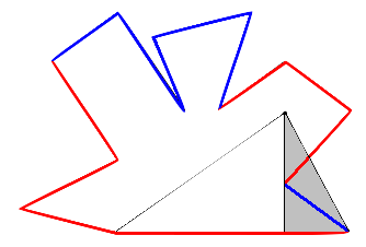
 When I saw this last case, I was glad I had opted for an exact integer-arithmetic-based solution.